In fiber laser systems, achieving a small and stable focal spot is essential for high-precision laser processing such as cutting, welding, and micro-machining.
Aspheric lenses are widely used to reduce spherical aberration and improve focusing performance.
Point-focus aspheric optics are widely used in modern laser systems to achieve high-quality beam focusing. In this configuration, a point source or quasi-point source—such as a fiber laser output—can be focused directly by an aspheric lens without the need for additional collimation or beam expansion optics.
This approach simplifies the optical system while still achieving excellent beam quality at the focal point.
Point-focus aspheric optics can generally be divided into two main categories:
Transmissive aspheric lenses
Reflective aspheric mirrors
These two optical configurations are illustrated in Figure 1 and Figure 2.
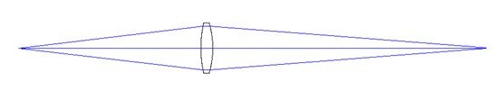
(1) Transmission-type point-focusing aspherical mirror
(2) Reflective point-focusing aspherical mirror
1. Transmissive Point-Focus Aspheric Lenses
Transmissive aspheric focusing optics typically include two common designs:
Single-surface aspheric double-convex lens
Double-surface aspheric double-convex lens
Both designs are capable of achieving excellent beam quality under ideal optical conditions.
However, compared with reflective focusing optics, transmissive lenses generally demonstrate better tolerance to system alignment errors in practical laser systems.
For example, reflective optics may exhibit several issues in real optical setups:
Energy distribution of the focused beam may become eccentric even under ideal conditions
Spacing errors, angular misalignment, or decentering can significantly degrade beam quality
Simulations show that any of these errors can introduce substantial optical aberrations
For this reason, transmissive aspheric lenses are widely used in high-precision laser processing systems.
2. Single-Surface Aspheric Double-Convex Lens
The even-order aspheric surface can be defined by the standard aspheric equation:
(You can keep your formula image here)
Where:
c is the curvature (inverse of radius)
k is the conic constant (hyperbolic, parabolic, elliptical, or spherical)
r is the radial coordinate on the lens surface
In the design presented here, the first surface of the lens is aspheric, while the second surface remains spherical.
The following designs were developed for a fiber laser with a wavelength of 1.064 μm.

Figure X. Mathematical definition of the aspheric surface used in laser focusing optics.
The surface profile of an aspheric lens can be described using the standard even-order aspheric equation:
Lens Design Parameters
FFL 75 mm Design
Diameter: 27.94 mm
Center thickness: 8.53 mm
Edge thickness: 3.0 mm
First surface (aspheric)
Radius: 36.224 mm
Conic constant: −1.924
Second surface (spherical)
Radius: −31.581 mm
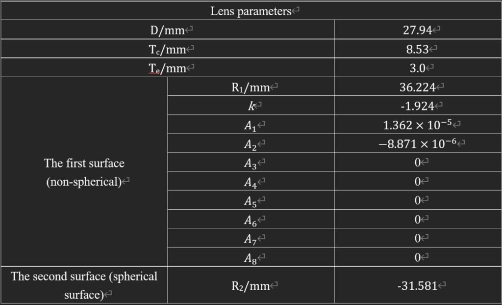
Table X. Key structural and aspheric coefficients of the designed laser focusing lens.
FFL 100 mm Design
Diameter: 27.94 mm
Center thickness: 7.888 mm
Edge thickness: 3.0 mm
First surface (aspheric)
Radius: 43.399 mm
Conic constant: −1.782
Second surface
Radius: −41.185 mm
FFL 125 mm Design
Diameter: 38.1 mm
Center thickness: 9.989 mm
Edge thickness: 3.0 mm
First surface
Radius: 59.956 mm
Conic constant: −1.303
Second surface
Radius: −52.235 mm
3. Double-Surface Aspheric Double-Convex Lens
In double-surface aspheric lenses, both lens surfaces are aspheric, allowing further reduction of aberrations.
Example parameters include:
FFL 75 mm
Diameter: 27.94 mm
Center thickness: 8.537 mm
Surface 1
Radius: 32.760 mm
Conic constant: −2.008
Surface 2
Radius: −32.751 mm
Conic constant: −2.008
Additional designs were developed for 100 mm and 125 mm focal lengths.
4. Design Conditions
All transmissive aspheric lens designs were developed for:
Wavelength: 1.064 μm
Laser source: fiber laser
Beam divergence: 0.24 rad
Lens material: fused silica
During simulations, the following practical tolerances were also considered:
Lens axial adjustment ±2 mm
Beam decentering 0.2 mm
Beam angular deviation 0–0.5°
Under these conditions, the focused beam quality remains close to the diffraction limit.
5. Reflective Ellipsoidal Focusing Mirrors
Reflective point-focus systems often use off-axis ellipsoidal mirrors.
In an ellipsoid:
Light emitted from one focus will reflect from the surface and pass through the second focus
The optical path length between the two foci remains constant
However, if the point source deviates from the focal position, optical aberrations increase rapidly and the beam quality deteriorates.
Therefore, the point source must be placed very close to the ellipsoidal focal point to maintain good focusing performance.
Despite this sensitivity, ellipsoidal mirrors theoretically have no spherical aberration, which makes them attractive for certain optical systems.
(3) Ellipsoidal reflecting focusing mirror FFL75mm-BFL125mm
6. Performance Comparison Between Transmissive and Reflective Optics
Simulations were performed to compare the focusing performance of:
A single-surface aspheric double-convex lens
An ellipsoidal reflective focusing mirror
Under ideal conditions, the reflective mirror produced a focused beam with slight asymmetry in the energy distribution.
Even when no alignment errors were present, the maximum energy point of the spot shifted slightly away from the geometric center.
When realistic system errors were introduced:
Source-mirror distance error: 0.5 mm
Mirror angular error: 0.1°
Mirror decentering: 0.2 mm
the reflective mirror produced a strongly elliptical energy distribution.
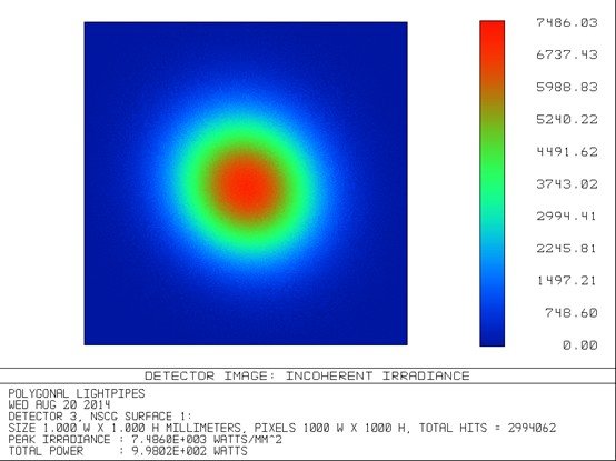
In contrast, the transmissive aspheric lens maintained a more symmetric beam profile.
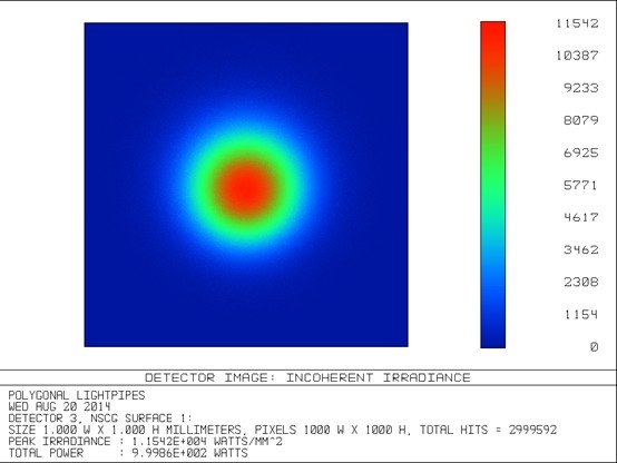
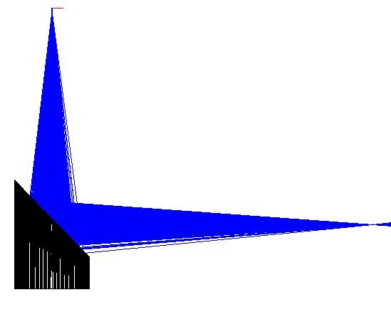
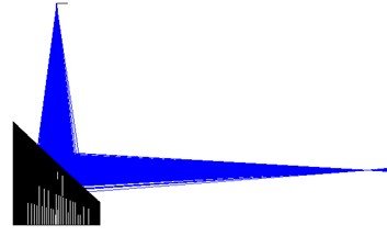
(4) Energy distribution of the focused spot 5mm in front of the focal point
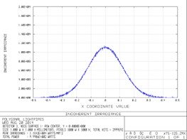
(5) Lateral distribution curve of the focused spot 5mm in front of the focal point
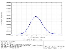
(6) Longitudinal distribution curve of the focused spot 5mm in front of the focal point
7. Implications for Laser Processing
In laser cutting applications, symmetric energy distribution is critical because uneven energy density may cause variations in cut quality.
Transmissive focusing optics offer several advantages:
Adjustable focus position through small axial lens movements
Greater tolerance to alignment errors
More stable beam quality
Reflective systems, on the other hand, cannot easily adjust the focal position by simply moving the mirror.
Adaptive optics or mechanical adjustments are often required, which may negatively influence beam stability or interfere with the assist-gas flow used in laser cutting.
(7) Energy distribution of the focused light spot 6 mm in front of the focusing point of the ellipsoidal mirror
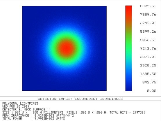
(8) Energy distribution of the focused spot 6mm in front of the focal point of a single-sided aspherical biconvex mirror
8. Application Considerations
For laser welding applications, the required beam quality is generally less demanding than in laser cutting.
In such cases, single-surface reflective ellipsoidal mirrors may still provide practical advantages due to their simple structure and compact optical layout.
Conclusion
Both transmissive aspheric lenses and reflective ellipsoidal mirrors can be used to focus point-source laser beams.
However, transmissive aspheric lenses generally offer:
better tolerance to alignment errors
more stable beam quality
easier focal position adjustment
These advantages make transmissive aspheric optics particularly suitable for high-precision laser processing applications such as laser cutting.
Reflective ellipsoidal mirrors remain useful in certain applications such as laser welding, where system simplicity and compact optical design are important considerations.