Optical Design Analysis Based on Non-Sequential ZEMAX Simulation
Abstract
Laser beam shaping plays a critical role in laser material processing applications such as laser cladding, laser welding, and laser surface treatment. In many industrial systems, the original laser output beam may exhibit a rectangular profile that needs to be converted into either a circular or controlled rectangular focused spot for optimal process performance.
In this study, several optical configurations were simulated using non-sequential mode in ZEMAX optical design software. The input beam was defined as a collimated rectangular beam, and multiple lens combinations were analyzed to investigate their capability to convert the rectangular beam into a circular or rectangular focused spot.
The simulation results demonstrate that different optical combinations—including cylindrical lenses, concave lenses, spherical lenses, and reflective optical elements—can effectively reshape the beam profile and achieve various focused spot geometries.
1. Simulation Conditions
All simulations in this study were conducted using non-sequential mode in ZEMAX.
Key assumptions:
Input beam: collimated rectangular beam
Input beam half-size: 1.8 mm × 4.5 mm
Beam shaping objective:
Convert rectangular beam into circular focused spot
Convert rectangular beam into different rectangular spot sizes
2. Rectangular Beam Conversion into Circular Spot
Several optical methods can convert a rectangular beam into a circular spot. Typical approaches include combinations of spherical lenses, cylindrical lenses, and reflective optics.
Although many configurations can generate a circular spot, the final spot size and circularity differ significantly depending on the optical design.
The following sections analyze several optical configurations capable of achieving circular beam shaping.
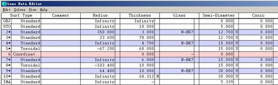
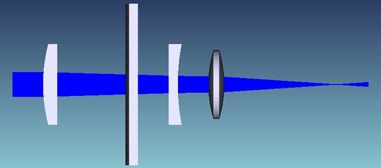
2.1 Double Concave Lens – Cylindrical Lens – Cylindrical Lens – Plano-Convex Lens
This configuration was first proposed in a reference provided earlier.
Optical Structure
Double concave lens → cylindrical lens → cylindrical lens → plano-convex lens
Simulation models include:
Optical parameter configuration
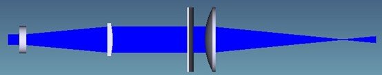
3D optical path diagram
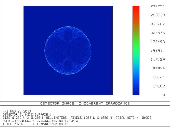
Output beam profile
The simulation shows that a rectangular beam with half-size 1.8 mm × 4.5 mm can be converted into a circular focused spot with a size of approximately:
0.1 mm × 0.1 mm
However, the circularity of the output spot still has room for improvement.
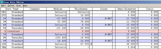
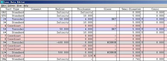
(1) Parameters of the combination of double concave lens-cylindrical lens-cylindrical lens-plano-convex lens
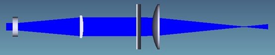
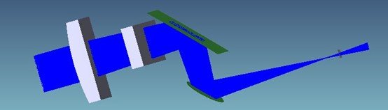
(2) 3D diagram of the combination of double concave lens-cylindrical lens-cylindrical lens-planoconvex lens

(3) Circular light spot output using a combination of double concave mirror-cylindrical lens-cylindrical lens-plano-convex mirror
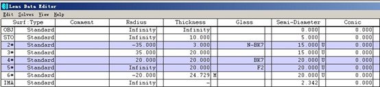
2.2 Plano-Concave Lens – Cylindrical Lens – Cylindrical Lens – Plano-Convex Lens
Next, the double concave lens was replaced by a plano-concave lens to evaluate the effect on the output beam.
Optical Structure
Plano-concave lens → cylindrical lens → cylindrical lens → plano-convex lens
Simulation results show:
Input beam half-size: 1.8 mm × 4.5 mm
Output spot size: approximately 0.1 mm × 0.1 mm
Compared with the previous configuration:
The output spot is closer to a true circular shape
The focused spot size is slightly smaller
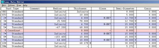
(4) Parameters of the plano-concave lens-cylindrical lens-cylindrical lens-plano-convex lens combination
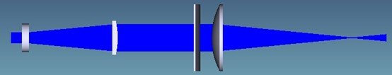
(5) 3D diagram of the combination of plano-concave lens-cylindrical lens-cylindrical lens-plano-convex lens

(6) The combination of plano-concave lens-cylindrical lens-cylindrical lens-plano-convex lens outputs a circular light spot.
2.3 Meniscus Lens – Cylindrical Lens – Cylindrical Lens – Plano-Convex Lens
Another configuration replaces the first lens with a meniscus lens.
Optical Structure
Meniscus lens → cylindrical lens → cylindrical lens → plano-convex lens
Simulation results show:
Input beam half-size: 1.8 mm × 4.5 mm
Output spot size: approximately 0.1 mm × 0.1 mm
The resulting beam spot is nearly circular, and the spot size is also smaller compared with the double-concave configuration.
(7) Parameters of the combination of crescent lens-cylindrical lens-cylindrical lens-planoconvex lens
(8) 3D diagram of the combination of crescent-cylindrical lens-cylindrical lens-plano-convex lens
(9) The combination of crescent-cylinder-cylinder-plano-convex lens outputs a circular light spot.
2.4 Double Concave Lens – Spherical Lens Combination
Introducing spherical lenses can further improve beam shaping.
Optical Structure
Double concave lens → spherical lens
Simulation results:
Input rectangular beam: 1.8 mm × 4.5 mm
Output circular spot: slightly smaller than 0.1 mm × 0.1 mm
(10) Parameters of the double concave mirror-spherical lens combination
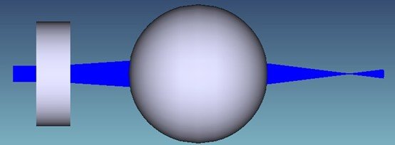
(11) 3D diagram of the combination of double concave mirror and spherical lens

(12) The combination of double concave mirrors and spherical lenses outputs a circular light spot.
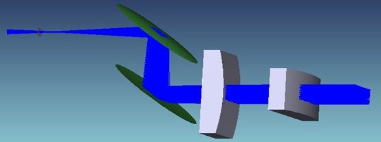
2.5 Cylindrical Lens Combination for Smaller Circular Spot
Another configuration uses multiple cylindrical lenses followed by a spherical focusing lens.
Optical Structure
Convex cylindrical lens → convex cylindrical lens → concave cylindrical lens → double convex lens
Simulation results:
Input beam half-size: 1.8 mm × 4.5 mm
Output circular spot envelope: 0.1 mm × 0.1 mm
The effective focused spot is significantly smaller than 0.1 mm × 0.1 mm.
Note: All beam shaping operations first reshape the large dimension of the beam (fast axis).

(13) Parameters of a combination of a convex cylindrical lens, a convex cylindrical lens, a concave cylindrical lens, and a biconvex lens.
(14) 3D diagram of a combination of a convex cylindrical lens, a convex cylindrical lens, a concave cylindrical lens, and a double convex lens.

(15) Convex cylindrical lens-convex cylindrical lens-concave cylindrical lens-double convex lens combination output
3. Beam Shaping Concepts Inspired by Rofin CO₂ Laser Systems
The axial fast-flow CO₂ laser system developed by Rofin provides another reference for rectangular beam shaping.
In this laser architecture:
The laser output beam is rectangular
A series of reflective mirrors transforms the beam profile into a circular beam
However, attempts to reproduce this approach using multiple reflective and refractive optical combinations were not yet successful in simulation.
Example configurations tested include:
Cylindrical lens + cylindrical lens + spherical mirror + spherical mirror
Cylindrical lens + cylindrical lens + double concave lens + spherical mirrors
These approaches still require further investigation and optimization.
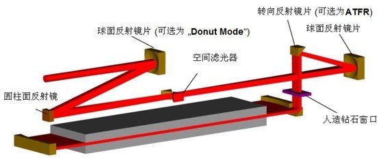
(16) Overall diagram of Rofin’s axial fast-flow CO2 laser
(17) 3D diagram of the combination of cylindrical lens-cylindrical lens-spherical mirror-spherical mirror
(18) 3D diagram of the combination of cylindrical lens-cylindrical lens-biconcave mirror-spherical mirror-spherical mirror.
4. Rectangular Beam Conversion into Different Rectangular Spots
In many laser applications—especially laser cladding, laser heat treatment, and surface processing—a rectangular beam may need to be reshaped into another rectangular spot with different dimensions.
Two representative optical configurations are discussed below.
4.1 Cylindrical Lens – Cylindrical Lens – Plano-Concave Lens – Plano-Convex Lens
Optical Structure
Cylindrical lens → cylindrical lens → plano-concave lens → plano-convex lens
Simulation results:
Input beam half-size: 1.8 mm × 4.5 mm
Output rectangular spot envelope: 0.04 mm × 0.04 mm
The actual focused spot is smaller than the envelope size.
By adjusting:
lens focal lengths
lens spacing
different strictly focused rectangular spots with varying aspect ratios can be obtained.
Note: ZEMAX non-sequential spot diagrams cannot directly display exact spot size.
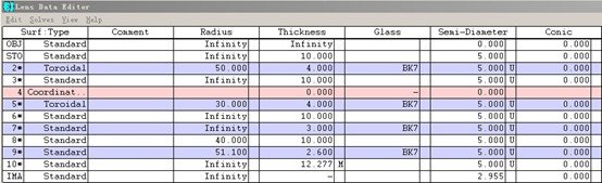
(19) Parameters of the combination of cylindrical lens-cylindrical lens-plano-concave mirror-plano-convex mirror
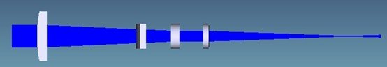
(20) 3D diagram of cylindrical lens-cylindrical lens-plano-concave lens-plano-convex lens combination
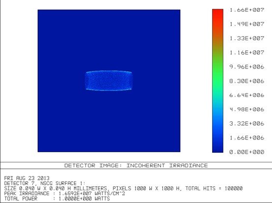
(21) A combination of cylindrical lens-cylindrical lens-plano-concave mirror-plano-convex mirror outputs a rectangular light spot.
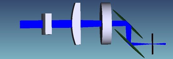
4.2 Cylindrical Lens – Cylindrical Lens – Cylindrical Mirror – Spherical Mirror
Another design approach inspired by Rofin fast-flow CO₂ laser optics uses reflective elements.
Optical Structure
Cylindrical lens → cylindrical lens → cylindrical mirror → spherical mirror
Simulation results:
Input beam half-size: 1.8 mm × 4.5 mm
Output rectangular spot envelope: 1 mm × 1 mm
By modifying:
lens parameters
optical spacing
rectangular spots with different sizes and aspect ratios can be obtained.
(22) Parameters of the cylindrical lens-cylindrical lens-cylindrical mirror-spherical mirror combination
(23) 3D diagram of the combination of cylindrical lens-cylindrical lens-cylindrical mirror-spherical mirror

(24) A combination of cylindrical lens-cylindrical lens-cylindrical mirror-spherical mirror outputs a rectangular light spot.
5. Conclusion
Through non-sequential ZEMAX simulations, multiple optical configurations were evaluated for rectangular beam shaping.
Key conclusions:
Rectangular beams can be effectively converted into circular focused spots using combinations of cylindrical lenses and spherical lenses.
Different optical structures produce different spot sizes and circularity levels.
Cylindrical lens combinations can also reshape beams into custom rectangular focused spots with adjustable dimensions.
Reflective optical systems inspired by CO₂ laser resonator optics may offer alternative beam shaping strategies but require further research.
These beam shaping methods provide valuable references for designing optical systems used in:
laser cladding heads
laser heat treatment heads
laser welding systems
high-power laser processing optics