Optical Design of Annular Beam Systems for Laser Cladding and Welding with Internal Powder/Wire Feeding
In recent days, we have reviewed several optical configurations for annular laser beam systems used for internal powder or wire feeding in laser cladding and laser welding processes.
An annular beam system refers to the conversion of a solid laser beam into a hollow beam through specific optical transformations. The hollow central region can then be used as a channel for powder or wire feeding.
Below we examine several representative optical solutions.
1. Annular Beam Optical Design for Laser Cladding and Welding
In Figure (1), a solid laser beam enters from the top and is first converted into a hollow expanded beam using a conical mirror. The beam is then focused by an annular parabolic reflector, forming a ring-shaped focal beam.
The hollow central axis provides space for powder or wire feeding.
Numerous studies and technical papers indicate that:
When powder feeding is used, the workpiece surface should be positioned at the focal point or slightly below it (positive defocus).
When wire feeding is used, the workpiece surface should typically be above the focal point (negative defocus).
The optimal position varies depending on the application. Many research papers analyze these process windows in detail, so they will not be discussed further here.
However, it should be noted that the cladding or welding quality depends not only on the focal position but also on many other factors, including:
powder or wire feeding speed
relative motion speed between the laser head and workpiece
laser power
duty ratio of the annular beam
powder or wire diameter
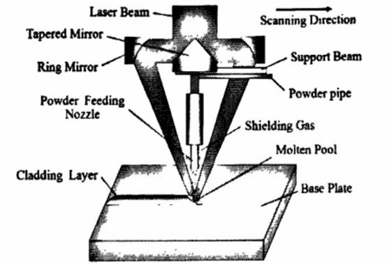
Figure(1)
2. Limitations of Traditional Annular Optical Systems
Many early research designs were based on CO₂ lasers, which typically have relatively large beam diameters.
As a result:
the laser cladding head becomes relatively large in size
the annular hollow angle is often large
achieving very thin cladding layers becomes difficult
Another challenge is that the powder or wire feeding channel passes through the annular optical path.
Although the energy distribution of the annular beam is relatively dispersed, the laser power used for cladding is typically very high. Therefore, the optical components and the feeding channel may still experience thermal effects or interference.
In addition, the manufacturing of off-axis annular parabolic mirrors is itself a significant optical fabrication challenge.
3. Alternative Optical Design Using Off-Axis Parabolic Mirrors
Another optical configuration can be considered.
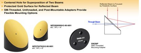
For example, off-axis parabolic mirrors with a central hole are commercially available from optical component suppliers such as Thorlabs.
Based on this concept, alternative annular beam optical systems can be designed for internal powder or wire feeding.
4. Conical Mirror and Off-Axis Parabolic Mirror Configuration
Because a conical mirror can transform a solid beam into a hollow beam, and an off-axis parabolic mirror works best with a collimated beam, the optical system must first generate a parallel annular beam before focusing.
This can be achieved by using two conical mirrors with identical cone angles:
one convex
one concave
The combination expands the beam into an annular parallel beam before focusing with an off-axis parabolic mirror.
Optical Principle
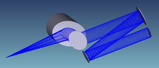
In Figure (2):
A parallel solid beam first strikes a convex conical mirror, forming a hollow diverging beam.
The beam then reflects from a concave conical mirror with the same cone angle, converting it into a hollow collimated beam.
The inner diameter of the hollow beam depends on:
the cone angle of the mirrors
the distance between the two conical mirrors.
For structural compactness, the expanded annular beam may then be redirected by a 90° folding mirror before entering the focusing stage.
Figure(2)
Finally, the beam is focused by an off-axis parabolic mirror with a central aperture.
Important design considerations include:
the cone angle should be very large (for example 179°)
the tilt angle relative to the incident beam should be small
(preferably less than 10°) to maintain beam quality.
5. Axicon-Based Annular Beam Expansion
The same optical principle can also be implemented using axicon lenses instead of conical mirrors.
However, laser cladding requires high laser power, which introduces additional requirements:
strong thermal resistance
minimal thermal lensing
good beam collimation capability
Therefore fused silica is typically a suitable material for the axicons.
However, this also limits the laser wavelength range that can be used.
6. Axicon and Parabolic Mirror Optical System
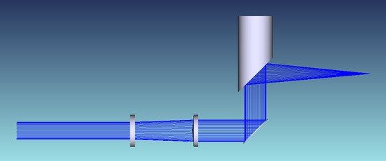
In the configuration shown in Figure (3):
the first axicon lens is concave
the second axicon lens is convex
both axicons have equal absolute cone angles.
The beam is expanded into an annular beam after passing through the two axicons.
For structural layout purposes, a 90° mirror may again be used to redirect the beam before it reaches a 90° off-axis parabolic mirror with a central hole, where the final focusing occurs.
Powder or wire feeding can then be implemented through the central aperture.
Good cooling design is essential for this optical system.
By adjusting the distance between the two axicons, the system can control:
the size of the annular beam
the diameter of the hollow region.
Figure(3)
This makes it possible to process:
thin-wall cladding
narrow welding seams
thicker cladding tracks
wide weld seams.
For thicker cladding layers, multiple passes are typically required. Additional tracks can be deposited adjacent to existing ones to build up material thickness.
The optimal parameters must be determined experimentally.
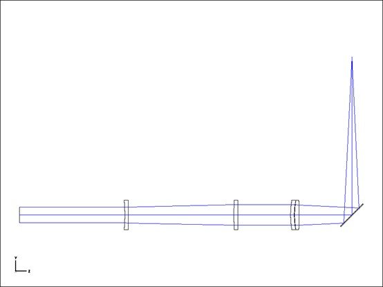
7. Alternative Transmission Focusing Configuration
Based on the optical scheme in Figure (4), the beam can also be focused through transmission optics instead of reflective optics.
In this case:
the beam is first focused by a lens system
it is then reflected by a flat mirror with a central hole
powder or wire feeding occurs through the central aperture.
Figure(4)
8. Lens-Based Focusing System
To ensure good beam quality after focusing, a two-element air-spaced lens group can be used, as illustrated in Figure (5).
If the requirements are less demanding, a single plano-convex lens or doublet lens may also be sufficient.
The focal length of the focusing lens should be selected based on the application requirements.
Process parameters such as:
powder or wire feeding method
feeding speed
optimal laser power
optimal defocus distance
must ultimately be determined through experimental testing.
Figure(5)
At Nipex Laser, we continuously study and develop advanced optical solutions for laser cladding, laser welding, and laser heat treatment systems. Annular beam technology is particularly valuable for coaxial powder feeding and internal wire feeding applications.
Our engineering team focuses on modular laser head design, high-power optical integration, and reliable beam shaping technologies for industrial laser processing.